The NE 555 are precision timing circuits that produce accurate time delays or oscillation. Single external resistor and capacitor network controls the timed interval in the mono-stable mode. In the a-stable operation, the frequency and duty cycle is managed independently by external resistors and a single external capacitor.
The trigger levels and threshold of the circuits are 15 7 one third and two-thirds of the VCC. To alter these levels, you can use the control voltage terminal. Once the trigger input goes below the trigger level, the output goes high, and the flip flop is set. If the reverse happens and there is no connection between the threshold level, the work becomes low, and the flip flop is reset.
NE555 datasheet
According to its datasheet, some of the main specs of the ne555 chip are:
- Supply voltage 4.5 to 16v
- Supply current 3 to 6mA
- Supply current (+15V) 10 to 15mA
- Output current (maximum) 200mA
- Maximum Power dissipation 600mW
- Power consumption(minimum operating) 300mW@5V, 225mW@ 15V
- Operating temperature o to 70 degrees Celsius
The following are the key application areas for the ne555 chip:
- Astable Operation
- Missing pulse detector
- Frequency divider
- Pulse width moderation
- Pulse position moderation
- Sequential timer
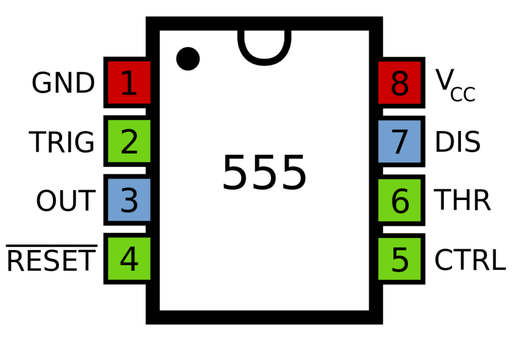
NE555 pinout
NE555 has eight different pins, and each has other functions. Pin 1 is the ground pin that connects the chip to the ground. Pin 5 is the control voltage pin connected to the environment through the use of a small capacitor—the capacitor levels out any fluctuations that might affect how the timer operates. Finally, pin 7 has an external capacitor that works with the resistor to control the timing intervals.
You can see the ne555 pinout diagram below.
NE555 Equivalents and Replacement Details
The equivalent for ne555 is the NTE955M 555LC and HA555. To check if your IC timer is functioning well, insert it in a socket and switch on the power supply, and if it glows alternately, you have the correct IC.